BTnode rev3 Hardware Reference
(:toc:) (:num:)
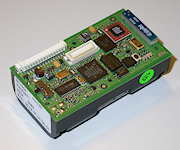
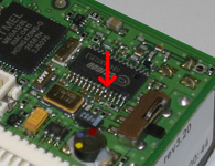
The BTnode rev3 is a dual radio device compatible to the old BTnode rev2 and the Berkeley Motes. This twin device can operate both radios simultaneously or shut them down independently when not in use. Both the BTnut System Software and TinyOS are supported.
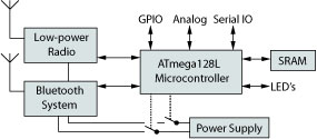
New features for the BTnode rev3 are a new Zeevo ZV4002 Bluetooth system supporting up to 4 independent Piconets and 7 Slaves and an additional Chipcon CC1000 low-power radio. The system is built around an Atmel ATmega128l microcontroller with an integrated battery case to house 2xAA cells and extension connectors. The BTnode is built on a 4 layer PCB measuring 58.15x32.5mm.
The hardware is scheduled for sample availability by the end of Q3/2004 and volume availability through a contract manufacturer thereafter. Pricing will be about USD 200 for samples.
Purchasing instructions for BTnode products
- Download the BTnode rev3.24 Product Brief [pdf] [rev3.24 2006-03-21]
System Core
The BTnode System Core consists of an Atmel ATmega128L microcontroller, clocks and SRAM memory.
- Atmel ATmega128L, 4kByte EEPROM, 64kByte SRAM, 128kByte Flash.
- System Clock, 32 kHz real time clock and 7.3728 MHz system clock.
- External Data Cache 3x60 kByte low power SRAM.
- Four LEDs for easy debugging.
- In System Programming through serial ISP programmer, JTAG or resident bootloader.
Bluetooth Radio
Zeevo ZV4002 Bluetooth radio running HCI firmware.
The radio is power class 2, without an external power amplifier.
It supports the following features: Features: 0xff 0xff 0x05 0xf8 0x1b 0x18 0x00 0x80 <3-slot packets> <5-slot packets>
Low Power Radio
Chipcon CC1000 radio operating at 868 MHz. Other operating frequencies can be used according to the CC1000 documentation (433-915 MHz). Both an integrated monopole antenna, and external wire and an external coaxial connector (MMCX type) are possible. The default assemply variant is the internal antenna.
Power Supply
The standard power supply are 2-cell AA batteries. The common range for these is 2-3V DC when either primary or rechargeable batteries are used. The primary boost converter has an input range of 0.5-3.3V DC. Alternatively 3.8-5V can be supplied through the VDC_IN pin on the external connectors J1 and J2.
- Primary Supply Linear LTC3429, 600mA max., 0.5-4.4V to 3.3V.
- Alternate Supply LT1962, 300mA max. 3.6-5.0V to 3.3V.
- Secondary Supply IO Default OFF.
- Secondary Supply BT Max. dissipation 80 mA. Default ON.
- Secondary Supply CC Max dissipation 30 mA. Default OFF.
- Battery Charge Indicator
- On/Off Switch for the primary power supply.
- Current Access Shunts to all subsystems for in-situ power profiling (AVR, BT, CC).
Power Consumption
| BTnode rev3 Bluetootha | BTnode rev3 Low Power Radioa | |
|---|---|---|
| Battery Supply | 2 AA cells | |
| Minimum Vin | 0.85 V | |
| Battery Capacity | 2900 mAh | |
| Regulated Supply | yes | |
| CPU sleep, Radio off | 9.9 mW | 9.9 mW |
| CPU on, Radio off | 39.6 mW | 39.6mW |
| CPU on, Radio listen | 92.4 mW | 82.5 mW |
| CPU on, Radio RX/TX | 105.6 mW | 102.3 mW |
| CPU on, Bluetooth Inq | 198 mW | -- |
| CPU on, Radios both listening | 135.3 mW | |
| Max. Power | 198 mW | 102.3 mW |
External Connections
External Interfaces UART, SPI, I2C, GPIO, ADC, Clock, Timer, LEDs
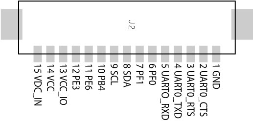
There are two ways to physically connect to a BTnode. The extension connector J1, or the debug connector J2. Both types are available at Farnell or Digikey in small quantities (Molex 1.25mm Wire-to-Board and Hirose DF17 Board-to-Board connectors)
Extension Connector J1 Hirose Receptacle DF17-40DS
Mating with Hirose Header DF17-40DP series, e.g. DF17C(2.0)-40DP-0.5V(50) available at Farnell under item no. 3908264 DF17(2.0)-40DP-0.5V(51) available at Digikey under item no. H2396CT-ND
Debug Connector J2 Molex 53261-1590
Mating with Molex 51021-1500 connector housing
available at Farnell under item no. 615171
available at Digikey under item no. WM17002-ND. Suitable plug connectors are available at Farnell under item no. 889570
BTnode rev3.22 Design Data
Assembly Top View
- BTnode rev3 Assembly Top [pdf] [rev3.22 2005-04-04]
- BTnode rev3 Schematic [pdf] [rev3.22 2005-04-01]
- BTnode rev3 Bill of Material [pdf] [04-01.22-006.BOM.01.08.BTNodeV322 2005-04-01]
AVR Fuse Bits Settings
The recommended fuse bit settings for the ATmega128l are
- Extended fuse 0xFF - M103C OFF- WDTON OFF
- High fuse 0x00 - OCDEN ON - JTAGEN ON - SPIEN ON - CKOPT ON - EESAVE ON - BOOTSZ1 ON - BOOTSZ0 ON - BOOTRST ON
- Low fuse 0x8E - BODLEVEL OFF - BODEN ON - SUT1 ON - SUT0 ON - CKSEL3 OFF - CKSEL2 OFF - CKSEL1 OFF - CKSEL0 ON
Fuses are logical one if selected OFF and zero if selected ON. For optimal power consumption results, fuses need to be adapted in the final application (see Atmel ATmega128l datasheet for information). We recommend to turn off OCDEN and JTAGEN at a minimum.
Hardware Errata
ISP Programming - SCK patch
The devices up to BTnode rev3.22 have a hardware error in the ISP programming logic. It is easy to fix and increases the reliability of ISP programming. All users that use ISP programming should implement this patch as described to prevent their devices from ISP programming failures.
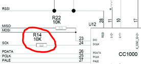
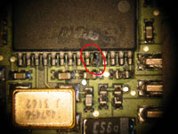
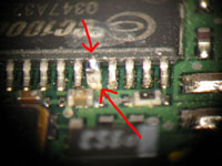
The patch adds a 10k Ohm resistor R14 in the SCK line decoupling the CC1000 radio from the ISP programming logic of the AVR. This is especially an issue when the CC1000 radio is not powered (possibly at bootup) and the SCK signal coming from the ISP programming device is then running into both the AVR and the unpowered input pin on the CC1000.
To install the resistor lift up the SCK pin on the CC1000 and add a 0402 size 10K Ohm resistor R14 under the pin. It's the 5th from the right:
Links and Resources
- Results of the user survey for BTnode rev3 [pdf] [2003-09-05]
- For an up to date list of issues discussed on the development of the BTnode rev3 see our Task Tracker on Sourceforge
- Atmel
- Zeevo Bluetooth solutions
- Chipcon single chip radio transceivers
